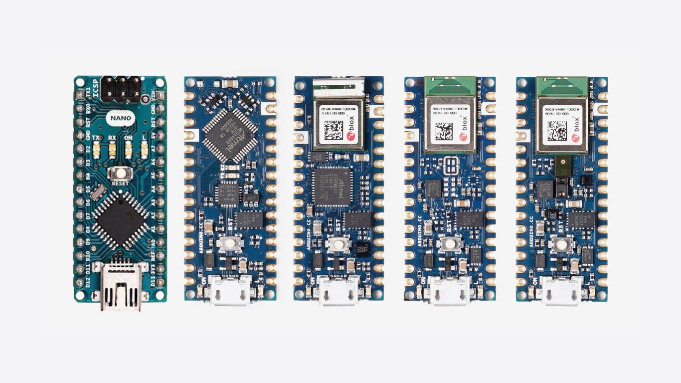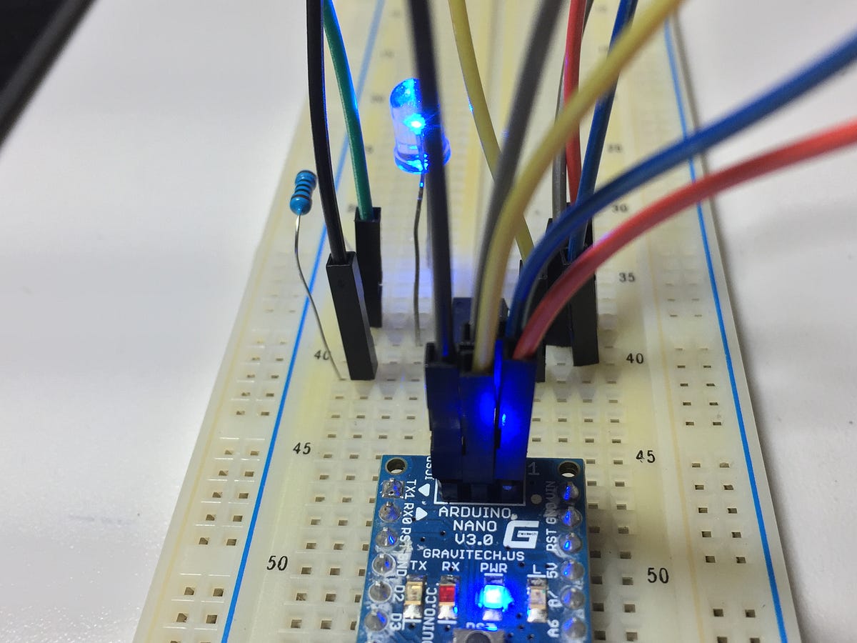
Arduino nano pinout led code#
Something which I prefer over just copy/pasting the Arduino code (can't wait? You can download the code with the course material button at the bottom of this page). This will make it easier for you to understand the working of the circuit. This is our first Arduino tutorial and therefore I have to explain some things to get you started. You find this information on many webpages with a click of the mouse. That is exactly what Bas on Tech tends not to do. I could a start an endless story on electronics, bombarding you with circuit diagrams and stories about signals. If you want a little bit more guidance, please continue reading. If you don't mind things being damaged, by all means go ahead and discover yourself 😄. A tough lesson was that I could even damage components when I wired things the wrong way. Soon I discovered that getting things to work was not as simple as it looked in the first place.

LCD display working now, not after reading boring theory. I skipped explanations of the basics because I wanted to get my The only thing I could think of was to start as fast as possible by just trying. What I saw was: a printed circuit board with chips, pins, a button and LEDs. It means when the red LED will be ON, the green LED will be OFF and vice versa.Arduino there was no YouTube with fancy instruction videos. Here, the green and red LED will light alternatively.
Arduino nano pinout led serial#
Select the board and serial port in the Arduino IDE.So, we will connect the shorter terminal to the Ground (GND). The shorter terminal indicates the ground. Note: The different colors of wire are used only for a better understanding. Similarly, the green wire is connected to the PIN 7, and the orange wire is connected to the GND. Here, the red wire is connected to the PIN 13, and the blue wire is connected to the GND. Connect the negative/shorter terminal (Cathode) of the red and green LED to the GND pin of the UNO board using the wire, as shown below:.
Arduino nano pinout led series#
Connect the left leg of the resistor (connected in series with green LED) to the digital output pin of the UNO board, i.e., PIN 7.Connect the left leg of the resistor (connected in series with red LED) to the digital output pin of the UNO board, i.e., PIN 13.

For any confusion, check the pin diagram shown above in the heading- Structure of project. We need to check that the plug-in is performed correctly, as shown above.

Here, we will use the red and green color LED. We can also use other types of Arduino boards, such as Arduino Mega, Arduino Micro, etc. The components used in the project are listed below: The long terminal is called Anode (positive charged), and the short terminal is called Cathode (negative charged). The structure of red and green LED is shown below: We can also use other resistors depending on the circuit limit and requirements. The resistors reduce the amount of current reaching the LED, which saves the LED from being burnt. As we know, we can use the resistance of any value, so let's take the resistors of 470 Ohms. The concept of blinking two LED's is similar to the blinking of a single LED. Here, we will discuss a project of blinking two LED's. We have already discussed a project of blinking an LED.


 0 kommentar(er)
